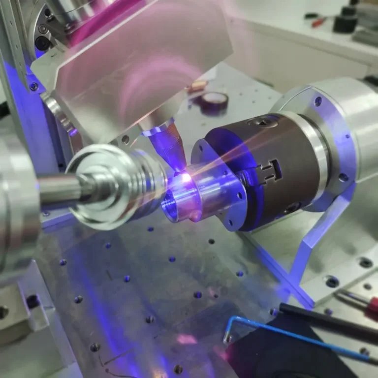
In short: Kerf is the width of material a laser cut removes. The beam melts and vaporises a narrow channel, the assist gas blows the molten material out, and what is left is a slot slightly wider than the beam itself. Every part therefore comes out marginally smaller than the drawing unless that width is accounted for in the toolpath.
Why Kerf Is Wider Than the Beam
The focused spot is the starting point, but the cut is not the same width as the spot. Heat conducts sideways into the material beyond the beam, and the assist gas jet widens the channel as it clears the melt. If you want the full sequence from beam to finished edge, how laser cutting works walks through it. The result is a kerf measurably wider than the beam diameter, and the difference grows with material thickness.
The practical consequence is that kerf is not a fixed number for a machine. It is the result of the beam, focus position, nozzle, gas, material and thickness in use at that moment. A figure measured on 2 mm mild steel does not transfer to 10 mm, and a figure from nitrogen cutting does not transfer to oxygen.
What Drives Kerf Width
| Factor | Effect on kerf |
|---|---|
| Material thickness | Thicker material widens the kerf, mainly through taper |
| Focus position | Focus set deeper in the material widens the entry kerf |
| Assist gas type | Oxygen adds an exothermic reaction and widens the cut; nitrogen cuts narrower |
| Gas pressure | Higher pressure clears more melt and widens the channel |
| Cutting speed | Slower travel puts more energy per unit length into the cut, widening it |
| Nozzle diameter and standoff | Shapes the gas column and therefore how much melt is removed |
| Material type | Reflectivity and thermal conductivity change how heat spreads |
Because these factors interact, the only reliable kerf figure is the one measured on your own machine, with your own parameters, on the material you actually cut — carbon steel, stainless and reflective metals such as aluminum each behave differently in metal laser cutting. Any number quoted without that context is an approximation.
Taper: Kerf Is Not the Same Top and Bottom
A laser cut is rarely perfectly parallel through the thickness. The beam converges to a focal point and diverges again, so the channel is narrower near the focus and wider away from it. On thin sheet this is negligible. As thickness increases, the top and bottom of the cut differ enough to matter for fit-up, and for parts that need square edges it becomes the limiting factor rather than kerf width itself.
Where the focus sits within the thickness decides which face is cleanest. Focus near the top surface favours a clean top edge; focus deeper favours bottom-edge quality and fuller penetration on thicker plate. Edge squareness is one of several quality measures covered in laser cutting precision and quality.
Compensating for Kerf
The cut follows a toolpath, and the toolpath has to be offset by half the kerf so the finished part lands on the drawing dimension. This is kerf compensation, and CAM software applies it automatically once the value is set. What goes wrong is almost never the software.
The Compensation Value Is Stale
Nozzle wear, a degraded protective lens or a change in gas supply all shift the kerf. A compensation value set months ago drifts. If one nest fits and the next comes out loose on the same program, check the nozzle before you touch the offset.
The Offset Is Applied to the Wrong Side
The offset direction differs for an external profile and an internal hole. Software handles this, but only if the geometry is defined with correct inside and outside orientation.
Small Features Are Treated Like Large Ones
Holes with a diameter smaller than the material thickness are difficult regardless of compensation, because the beam cannot complete a clean pierce and turn in that distance. This is a design constraint, not a settings problem.
Where Kerf Matters Most
Interlocking and Tab-and-Slot Assemblies
Both mating faces carry kerf loss, so the error doubles at the joint. Tabs come out loose if compensation is ignored.
Nesting on Sheet
Across a sheet with many parts, the accumulated kerf is real material. Part spacing has to allow for it — parts nested too closely share a cut edge and come out undersized. The same logic applies on a sheet metal laser cutting machine of any size.
Holes for Tapping and Press Fits
Holes intended for tapping or press fits need the compensated dimension, not the drawn one.
Thick Plate
Taper becomes the dominant error, and a single compensation value cannot correct a cut that is not parallel.
Tight fit-up on the parts you are quoting? Send the drawing with the material and thickness range before you commit to a machine. We would rather warn you that the cut edge will not hold that tolerance than have you find out after the machine lands. Send us the drawing
Reducing Kerf Width
A narrow kerf is not a goal in itself — a narrow kerf that produces dross or an unstable cut is worse than a slightly wider clean one. Where a narrow cut genuinely matters:
- Cut with nitrogen rather than oxygen where the material and thickness allow.
- Keep optics clean; a contaminated lens spreads the focus.
- Replace worn nozzles on schedule rather than on failure.
- Set focus deliberately for the thickness instead of relying on a single stored value.
- Increase speed to the point where cut quality is still acceptable.
Common Questions
Is kerf the same as the beam diameter?
No. Kerf is always wider, because heat conducts sideways and the assist gas widens the channel as it clears the melt.
Does kerf change as the machine ages?
Yes, gradually. Nozzle wear and optical contamination both widen it, which is why compensation values need periodic re-measurement.
How do I measure my own kerf?
Cut a test piece of known dimension in the material and thickness you use, measure the finished part, and take the difference from the drawing. On thicker material, measure at both the top and bottom faces to see the taper.
Does kerf differ between sheet and tube cutting?
The mechanism is the same, but tube introduces a curved surface and a changing standoff around the profile, so kerf is less uniform than on flat sheet.
Related
Equipment
Further reading
Get in touch
- Contact Topstar for cutting parameter guidance on your material and thickness range.